AMATEUR
RADIO
![]()
On Her Majesty’s
Service


License To Talk…
![]()
![]()
![]()
B I O
Born In
By The Age
Of 6 Y/O I Was Taken Used Electoral Components To Build
A
1981 Stationers
Comprehensive Hi School
1988
Employed As A Radio Installer Engineer for 2 way
Radios
1989 Repairing
C.B Radios From The Home QTH Somewhere In Barnet N. London
1994 Community
Systems In
1994
Bought An Amiga Computer Using Work-Bench 1.3
1995
Bought An Amiga 1200HD & Used Work Bench 3.0 Along
With Many Music Programs
1995 Built
My First PC With 128 M/b Ram 3DFX Card
1996 Me &
My Good Friend Alan X Stated Up Our Own PC Repair Service
2000 Moved
To The
2000
Lived Somewhere In
2001
Moved To E.L.8.7
To Be Contained…
![]()
![[icom 706]](AMATEUR%20RADIO_files/image005.gif)
We have taken away some of
the links as I am fed up the people not keeping there web pages up to date
So we
removed them, all apart from the hot links below Hope That the Links
Help you,
and please do come back soon, If You Have Any Comments Or Find Any Broken Links
Please
Email Us,
Thank You


![]()


![]()
All The Links Below
Are Click-able
![]()
![]()
![]()
The Tech Page
![]()
So you would like to improvise and make your own
D.I.Y Antennas Have Fun from KG4 OHH & KG4 QOZ
![]()
But First the Blurb:
Install your antenna properly
1. Always SAFTY !!
2. Proper Tools Must Be Used !!
3. Weather Conductions Must Be Observed !!
The antenna system is the key to reception at all
frequencies.
The antenna itself can be very cheap: $2 worth of hookup wire can make a great
antenna. It's the installation of the wire that counts. Coax is not magic: it
basically works by conducting noise pickup to ground. It is therefore essential
to ground the coaxial shield
Well: fanatics will use two
ground stakes, one near the house, one at the base of the antenna, and bury the
coax cable in between. I've experimented
with pickup of my computer's 25 MHz clock, and found that ungrounded coax picks
up 36 dB more than grounded coax in my setup. That's a factor of 4000 in power!
Keep the antenna
itself away from all kinds of utility lines, power, CATV, Satellites dish’s and
telephone. Remember that your house is full of this stuff, so keep the antenna
away from your house. An "inverted L" run up a tree and then over to
another tree works very well Also if you plan to install a beam in the yard or
on the roof of your house the above also applies, if you can, for 6 meter 2 meter and 70 cm’s
use a H.T and walk around the yard to find out good pick up points/ Repeater
Signals, try a repeater that is far away but you know can hit well even if you
have to make a di-pole for whatever band and carry it around with you in the
yard with your H.T, this will help you to locate a good line of sight signal
and will help you in the long run.
If using a wire, a matching transformer
will prevent the "deaf spots" that you may get at ant resonant
frequencies. For an end fed wire antenna, these occur when it is near a
multiple of 1/2 wavelength in length). Generally, the longer the wire, the less
you'll notice these.
If you want to buy a matching
transformer, I like the Model 180 from ICE at (800) 423-2666 or (317) 545-5412
Also posted instructions for winding your
own Fancy brand name antennas will perform well if properly installed, but so
will simple wires. Spend your money on ground stakes.
An antenna tuner will improve signal transfer from the
antenna to the receiver the cheapest one I have found easy to use is the MFJ
945E covers 1.3 Mhz to 54 Mhz this will make a difference in your signal to
noise ratio. Also a passive preselector may help with overloading due to out of
band signals. At shortwave frequencies, active preselectors a preamplifiers
only increase your susceptibility to overload in an otherwise properly
functioning system. If a preamplifier helps, there's almost certainly something
wrong with your receiver or antenna system, and you'll get better results if
you fix that.
(Note that the advice changes at VHF and
microwave frequencies: scanner folks may well find that careful matching and
low noise preamplifiers are worthwhile. The reason is that the natural noise
level declines with increasing frequency, so greater sensitivity can be useful.
I find that the difference in the number of listen
able signals between an indoor antenna and a properly installed outdoor
antenna is often a factor of ten or more. The difference between a $200
receiver and a $1000 receiver is more like a factor of two in the number of
listen able signals, and some find no difference at all
The extra performance of the fancy
receivers costs not only money, but knowledge and skill as well as locating an
antenna system.
![]()
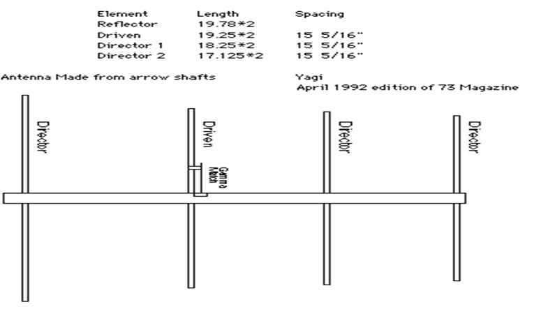
Here are some examples:
The 2 Meter Carbon
Arrow (144 ~ 148Mhz) 4 Element Beam

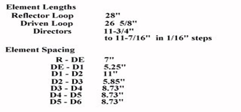
70 CM Antenna Examples:
The 6 Meter 3 Elements:
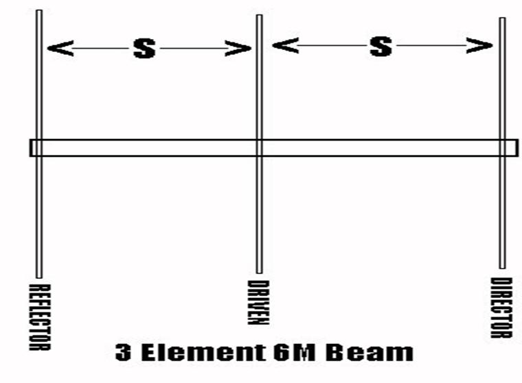
Reflector = 115 + ½ Inch (Divided by 2)
Driver = 111 Inch (Divided by 2)
Director = 106 + ½ Inch (Divided by 2)
This Type of Antenna is a Direct Feed to
the Driver Using 50 Ohm Coax
![]()
Home
Brew P.S.U
We Built This
P.S.U and It Works Well, The Only Thing We Would Recommend
Is
Replace The 2N3055’s With A Stronger Type That Can Handle 15 to 25 Watts Each
The
2N3055 Are Rated @ 12 ~ 15 Watts But Threes A
Rear End
of the P.S.U Blowing On To the Heat Sink.
Do Not
Let 2N3055 NpN Come In Contac Directly To The Case (GND)

![]()
Dielectric
Properties: P=Poly, F=foam
|
RG #
Type |
IMP. |
db/100 FT @ 100 MHz |
db/100 Ft @ 400 MHz |
db/100 Ft @ 1 GHz. |
OD |
Vel F |
INS/KV |
Di |
|
BAND |
|
V/HF |
UHF |
UHF |
|
|
|
|
|
|
|
|
|
|
|
|
|
|
|
6 /U |
75 |
2.1 |
5 |
6.9 |
0.27 |
0.78 |
0.6 |
F |
|
7 /U |
95 |
|
|
|
|
|
|
|
|
8 /U |
50 |
1.8 |
4.7 |
6.9 |
0.405 |
0.66 |
5 |
P |
|
8 /U |
50 |
1.1 @ 1.2
50MHz |
|
|
|
0.78 |
0.6 |
F |
|
11 /U |
75 |
1.0 @ 2.0
50MHz |
|
|
0.425 |
0.78 |
0.6 |
F |
|
17 A/U |
52 |
0.81 |
1.9 |
3.8 |
0.87 |
0.66 |
|
|
|
58 A/U |
50 |
4.9 |
11.5 |
20 |
0.195 |
0.66 |
1.9 |
F |
|
58 /U |
50 |
3.1 @ |
50MHz |
|
|
0.78 |
0.2 |
F |
|
59 B/U |
75 |
3.4 |
7 |
11.1 |
0.242 |
0.66 |
2.3 |
F |
|
100 /U |
35 |
|
|
|
0.242 |
0.66 |
|
|
|
212 /U |
50 |
1.6 |
3.6 |
8.8 |
0.336 |
0.66 |
|
|
|
213 /U |
50 |
2.2 |
4.7 |
8 |
0.405 |
0.66 |
5 |
P |
|
214 /U |
50 |
2.2 |
4.7 |
8 |
0.425 |
0.66 |
5 |
P |
|
215 /U |
50 |
2.2 |
4.6 |
9 |
0.475 |
0.66 |
|
|
|
8281 |
75 |
|
|
9.2 |
0.275 |
|
2.9 |
|
|
9913 |
50 |
1.4 |
2.8 |
4.5 |
0.475 |
|
0.6 |
|
|
|
|
|
|
|
|
|
|
|
|
LDF# |
IMP. |
db/100 Ft @ 150 MHz |
db/100 Ft @ 450 MHz |
db/100 Ft @ 824 MHz |
OD |
Vel F |
PWR/KW |
Di |
|
LDF4-50A |
50 |
0.845 |
1.51 |
2.10 |
0.5 |
.88 |
3.63 |
F |
|
|
|
|
|
|
|
|
|
|
![]()
General Exam Study
Band Guide
|
BAND |
FREQUENCY
LIMITS 1000 Hz=
1 Khz |
|
160 meter |
1800-2000-kHz 1 Hz=
0.001 Khz |
|
75/80 meter |
3525-3750-kHz Thus 1 Hz= 0.000001 Mhz |
|
40 meter |
7025-7150-kHz |
|
30 meter |
10100-10150-kHz |
|
20 meter |
14025-14150-kHz |
|
17 meter |
18068-18168-Khz |
|
15 meter |
21025-21200-kHz |
|
12 meter |
24890-24990-kHz |
|
10 meter |
2800-29700-kHz |
|
6 meter |
50.1 – 54
Mhz |
|
10.140 MHz |
200 WATTS ( ABSOLUTE MAXIMUM) |
|
21.15
MHz |
200
WATTS “ “ |
|
3690 kHz |
200 WATTS
“
“ |
|
7105 kHz |
200
WATTS “ “ |
|
24.95 MHz |
1500 WATTS
“
“ |
|
28.4 MHz |
1500
WATTS (ABSOLUTE MAXIMUM) |
|
3818 kHz |
1500 WATTS
“
“ |
|
7080 kHz |
1500
WATTS “ “ |
|
14.3 MHz |
The minimum power necessary, but you can run up to 1500
WATTS. |
|
1825 kHz |
The
minimum power necessary, but you can run up to 1500 WATTS |
|
|
|
|
Band |
Emission
Type Maximum Symbol Rate (Baud) |
|
< 28 MHz |
Packet 300 bauds |
|
< 28
MHz |
RTTY 300
bauds |
|
10 Mtr |
Packet 1200 bauds |
|
10 Mtr |
RTTY 1200 bauds |
|
2 meter |
Packet 19.6 kilo
bauds |
|
|
RTTY |
|
6
meter/2 Mtr |
RTTY, Data ,Multiplexed emissions with unspecified
digital code 20 kHz |
|
|
|
|
|
|
|
Emission Type |
Minimum Frequency separation |
|
CW |
150-500 Hz |
|
SSB |
approximately
3 kHz |
|
RTTY |
250-500 Hz |
|
|
|
|
Band |
Emission
Type Frequency segment most takes
place |
|
80 meter |
RTTY 3580-3620 kHz |
|
20 meter |
RTTY 14.070-14.095 MHz |
![]()
Have Fun
73’s Mark & Gayle